Short answer
Refrigeration parts start with four core components: a compressor, a condenser, an expansion device and an evaporator. Around them sit a filter drier, sight glass, solenoid valve, pressure switches, defrost heaters and a digital temperature controller with NTC probes, typically set to a 2 K differential and defrost every 6–8 hours on freezers.
Key takeaways
- The four core refrigeration components are the compressor, condenser, expansion device and evaporator.
- A liquid line solenoid valve plus a low pressure switch gives pump-down control on most walk-in coolers.
- Typical controller settings: 2 K (4 °F) differential, freezer defrost every 6–8 hours for 20–30 minutes.
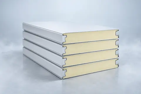
- Walk-in coolers use 75–100 mm (3–4 in) panels and freezers 120–150 mm (5–6 in), plus a heated door frame and pressure relief port.
- Order spares by part number, refrigerant, voltage and frequency, never by description alone.
- Replace the filter drier every time the refrigerant circuit is opened.
What are the basic parts of a refrigeration system?
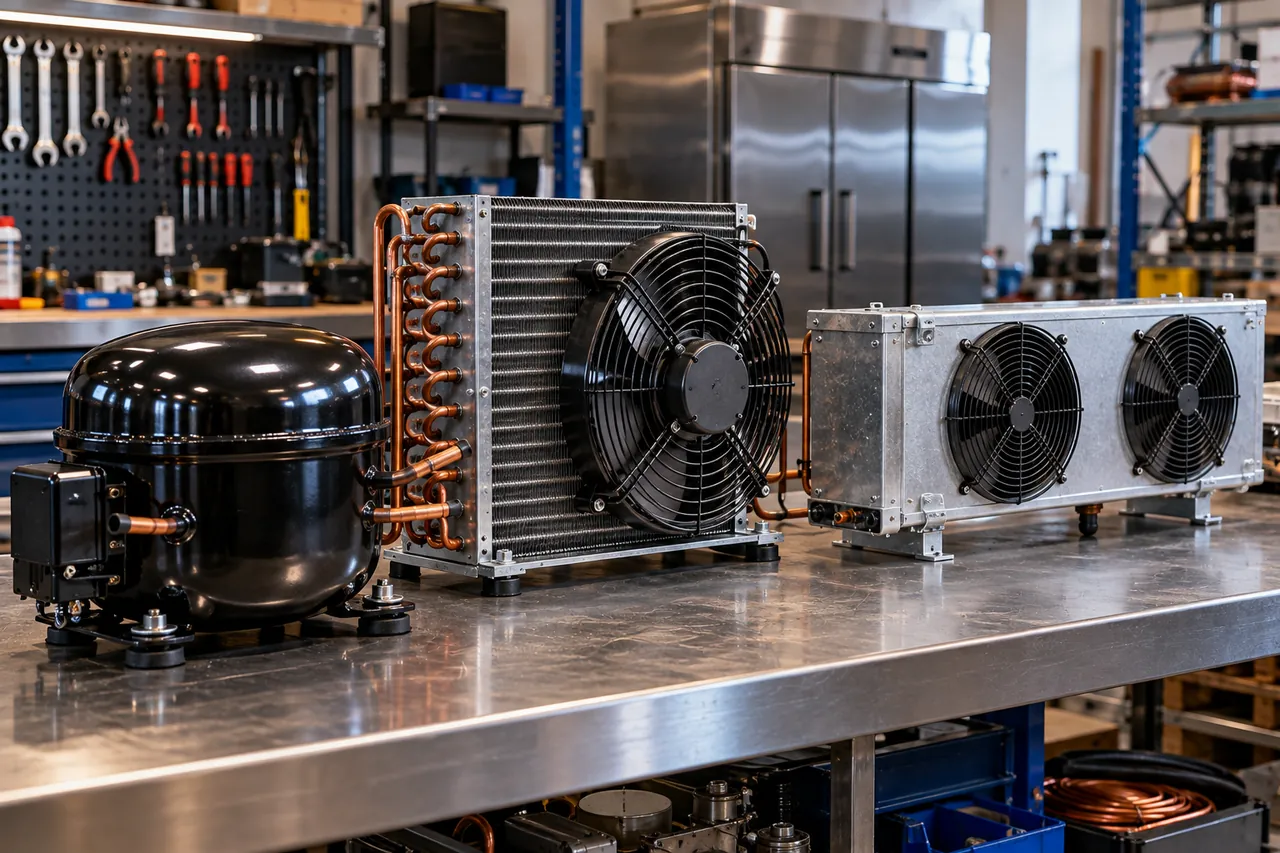
Every vapour-compression refrigeration system has four basic parts: a compressor that pumps refrigerant vapour to high pressure, a condenser that rejects heat to outside air or water, an expansion device that drops the pressure, and an evaporator that absorbs heat from the cabinet or room. Everything else in a list of refrigeration parts exists to control, protect or connect these four.
The refrigerant circulates in a closed loop through them. On the high-pressure side, from the compressor outlet through the condenser to the expansion device, it is hot gas and then warm liquid. On the low-pressure side, from the expansion device through the evaporator back to the compressor, it is cold liquid boiling into vapour. Our guide to condenser vs evaporator vs compressor explains each stage in detail.
Around that loop sit valves that open, close or regulate flow; line components that filter, store and indicate refrigerant; electrical controls that start and stop the system and run defrost; and, in the cabinet or cold room itself, insulation, doors, gaskets, heaters, fans and lights. The sections below list them in the order a technician meets them.
What are the main commercial refrigeration parts and what do they do?
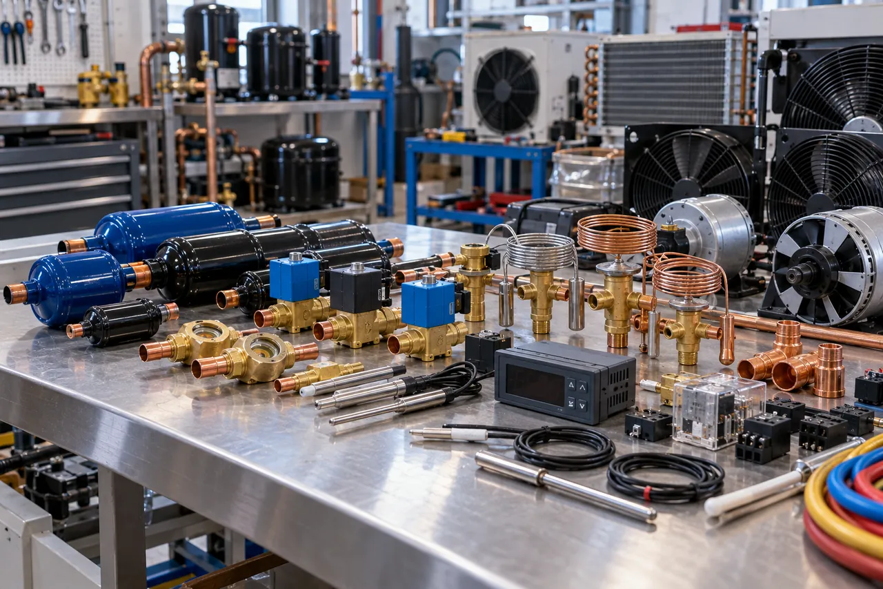
The main commercial refrigeration parts are the compressor, condenser coil and fan, receiver, filter drier, sight glass, solenoid valve, expansion valve, evaporator coil and fans, defrost heaters, digital controller with probes, pressure switches and the electrical starting components. The table summarises their jobs and typical failures.
| Component | What it does | Where it is | Typical failure signs |
|---|---|---|---|
| Compressor | Pumps vapour from low to high pressure | Condensing unit, back or base of cabinet | Won't start, trips overload, noisy, poor pumping |
| Condenser coil and fan | Rejects heat from hot refrigerant to air | Condensing unit, back or base of cabinet | Dirty fins, fan motor failure, high head pressure |
| Receiver | Stores liquid refrigerant, buffers charge | After condenser on split systems | Rarely fails; relief valve may vent if overpressurised |
| Filter drier | Removes moisture, acid and debris | Liquid line | Blocked: temperature drop across it, frosting |
| Sight glass / moisture indicator | Shows liquid flow and moisture | Liquid line, after drier | Bubbles (low charge or restriction), yellow indicator (wet) |
| Solenoid valve | Opens or closes refrigerant flow electrically | Liquid line (pump-down), hot gas or other lines | Coil burnt, valve stuck open or closed |
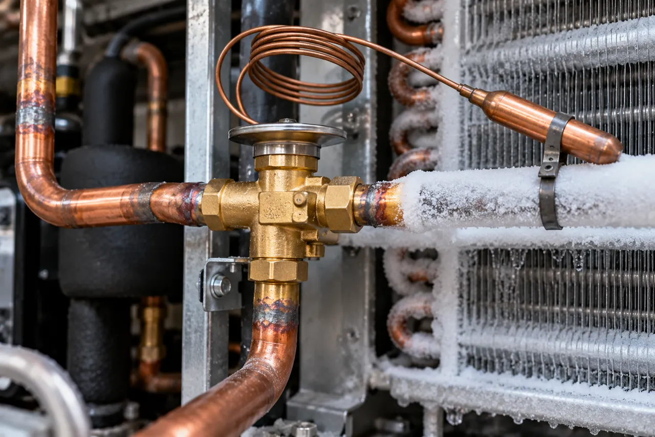
| Expansion valve (TXV or EEV) or capillary | Meters liquid into evaporator and drops pressure | Evaporator inlet | Starved or flooded evaporator, hunting |
| Evaporator coil and fans | Absorbs heat from the space | Inside the cabinet or cold room | Ice build-up, fan failure, poor airflow |
| Defrost heaters and drain heater | Melt frost from coil and keep drain open | On the evaporator and drain line (freezers) | Open circuit, ice blocks, water leaks |
| Digital temperature controller and probes | Runs compressor, fans, defrost and alarms | Front panel or electrical box | Wrong reading, probe failure, lost settings |
| High and low pressure switches | Stop the compressor at unsafe pressures; control pump-down | On the condensing unit | Nuisance trips, stuck contacts |
| Contactor, overload, start relay and capacitors | Switch and protect the compressor motor | Electrical box or compressor terminal cover | Clicking without starting, burnt contacts, swollen capacitor |
What valves are used in refrigeration systems?
The main refrigeration valves are solenoid valves, expansion valves, service valves, check valves, ball valves and pressure regulators. Each controls either whether refrigerant flows, how much flows, or at what pressure.
| Valve | Function | Common use |
|---|---|---|
| Solenoid valve | On/off flow controlled by an electric coil (typically 24 V, 120 V or 230 V) | Liquid line pump-down on cold rooms, hot gas defrost, multi-evaporator systems |
| Thermostatic expansion valve (TXV) | Meters refrigerant to keep evaporator superheat constant | Walk-ins, larger cabinets, transport units |
| Electronic expansion valve (EEV) | Stepper-motor valve driven by a controller | Variable-speed and high-efficiency systems |
| Capillary tube | Fixed restriction, no moving parts | Small plug-in fridges and freezers |
| Service valves (Schrader, ball or rotalock) | Access for gauges, isolation for service | Compressor and condensing unit ports |
| Check valve | Allows flow in one direction only | Heat pumps, parallel compressors, hot gas lines |
| Evaporator or crankcase pressure regulator | Holds a minimum evaporator pressure or limits compressor suction pressure | Multi-temperature systems, low-temperature start-up |
| Head pressure control valve | Keeps condensing pressure up in cold weather | Outdoor condensing units in cold climates |
| Four-way reversing valve | Swaps condenser and evaporator roles | Heat pumps, some reverse-cycle defrost |
How does a refrigeration solenoid valve work?
A refrigeration solenoid valve is a valve held closed by a spring and plunger; when its coil is energised, the magnetic field lifts the plunger and refrigerant flows. Most are normally closed. In a typical walk-in cooler, the digital controller energises the liquid line solenoid when the room needs cooling; when the room is cold, the solenoid closes, the compressor pumps the low side down, and the low pressure switch stops the compressor. This pump-down cycle keeps liquid refrigerant out of the compressor during the off cycle.
When buying a replacement, match the connection size, the refrigerant, the coil voltage and frequency, and the maximum opening pressure differential (MOPD). An air conditioning solenoid valve works the same way. In car AC, the term AC compressor solenoid usually means the control valve on a variable-displacement compressor or the clutch coil, not a line valve. Expansion valves are covered in depth in our TXV expansion valve guide.
What controls and safety devices does a refrigeration system need?
A commercial refrigeration system needs a temperature controller to cycle cooling and defrost, pressure switches to protect the compressor, motor protection and starting components, and alarms. On modern equipment the digital temperature controller combines thermostat, defrost timer and alarm in one unit.
A typical cold room controller reads two or three NTC probes (room air, evaporator coil and sometimes condenser) and controls the compressor or solenoid, evaporator fans, defrost heaters, light and alarm relay. Typical starting settings are:
- Set point: +2 °C to +4 °C (36–39 °F) for a chiller, −20 °C (−4 °F) for a freezer.
- Differential: about 2 K (4 °F), so the compressor starts 2 K above set point.
- Defrost: every 6–8 hours for freezers, 20–30 minutes, ending when the coil probe reaches about +8 °C to +12 °C (46–54 °F).
- Drip time: 2–5 minutes after defrost, then a fan delay until the coil is cold again.
- Alarms: high and low temperature limits with a 30–60 minute delay, and a door-open alarm.
Protective devices include the high pressure switch (stops the compressor if the condenser fails), the low pressure switch (pump-down and loss-of-charge protection), the compressor's internal or external overload, crankcase heaters on larger units, and on three-phase systems a phase monitor to prevent reverse rotation. The electrical starting parts, start relays, start and run capacitors and contactors, wear out more often than the compressor itself.
What are the parts of a commercial fridge, inside and at the back?
Inside a commercial refrigerator you will find the evaporator coil and fan behind a cover, the temperature probe, shelves and clips, lighting, door gaskets and, on freezers, door frame heaters and a drain heater. At the back or in the base are the compressor, condenser coil and fan, start relay and overload, drain line and condensate evaporating tray.
Parts of the refrigerator inside
- Evaporator coil and fan, usually behind a rear or top panel, with a fan guard.
- Air probe and, on frost-free models, a defrost-termination probe and heaters.
- Door gaskets: magnetic PVC gaskets that should be replaced when torn or hardened.
- Anti-condensation heaters in door frames and glass doors on freezers and some coolers.
- Shelving, pilasters and clips, LED lighting and door switch.
- Drain trough and drain hose leading to the evaporating tray.
Back of fridge parts
- Compressor with start relay, overload and capacitor under the terminal cover.
- Condenser coil (fin-and-tube or wire) and condenser fan; this needs regular cleaning.
- Filter drier and capillary tube or expansion valve.
- Condensate evaporating tray, often heated by the hot discharge line or an electric heater.
- Controller wiring and the power cord.
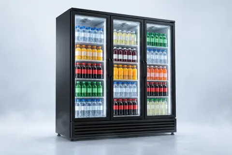
Display fridges and freezers use the same parts plus glass doors and lighting; the frost-free vs manual defrost guide explains the defrost parts in freezers.
What parts make up a walk-in cooler or freezer?
Walk-in cooler and freezer parts divide into the insulated box (panels, floor, door and fittings) and the refrigeration system (condensing unit, evaporator, piping and controls). In place of a walk-in cooler parts diagram, the table lists each part in the order it is assembled.
| Group | Part | Notes |
|---|---|---|
| Box | Wall and ceiling panels | PU or PIR, 75–100 mm (3–4 in) coolers, 120–150 mm (5–6 in) freezers, cam-lock joints |
| Box | Floor panels or insulated slab | Required for freezers; XPS under slab for large rooms |
| Box | Door, gaskets, hinges, closer, inside safety release | Heated frame on freezer doors |
| Box | Pressure relief port | Freezers: equalises air pressure so the door can be opened |
| Box | Strip curtain, kick plate, lighting, sealant, trims | Reduce infiltration and protect panels |
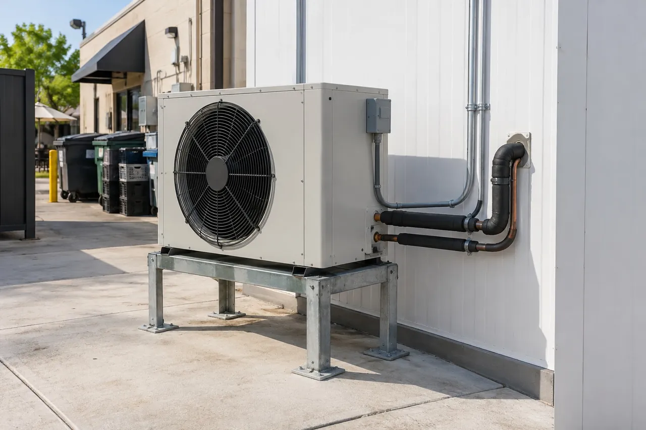
| Refrigeration | Condensing unit | Compressor, condenser, receiver, pressure switches |
| Refrigeration | Evaporator (unit cooler) | Coil, fans, drain pan; electric defrost heaters on freezers |
| Refrigeration | Expansion valve and liquid line solenoid | Usually mounted at the evaporator |
| Refrigeration | Copper piping, insulation, filter drier, sight glass | Insulate the suction line; heat-trace freezer drain lines |
| Controls | Digital controller, probes, alarm, electrical panel | Thermostat, defrost and alarm in one unit |
The refrigeration side is explained in our walk-in condensing unit and evaporator guide and the evaporator coil and unit cooler guide. When something fails, the walk-in freezer troubleshooting guide links symptoms to parts.
Which spare parts should you keep, and how do you buy from a refrigeration supply distributor?
Keep the parts that fail most often and stop a system completely: controller probes, start relays and capacitors, contactors, fan motors, door gaskets, defrost heaters and filter driers. When ordering from a refrigeration supplies distributor or wholesaler, always quote the data on the nameplate rather than a description.
- Model and serial number of the equipment and the component's own part number.
- Refrigerant type, for example R290, R404A, R448A, R134a or R449A.
- Voltage, frequency and phase: 220–240 V 50 Hz, 115 V 60 Hz or 380–415 V three-phase.
- Connection sizes and type (flare or solder) for valves and driers.
- For compressors, displacement and cooling capacity at stated evaporating and condensing temperatures.
- For probes, the sensor type the controller expects, such as 10 kΩ NTC.
Parts that look the same can differ in coil voltage, refrigerant compatibility or sensor curve, so an approximate match causes new faults. For equipment imported from another market, ask the supplier for a spare parts list with part numbers at the time of order; our checklist for importing refrigeration equipment covers what to put on the proforma invoice.
How to choose refrigeration parts and components: checklist
Choose refrigeration components as a matched system: capacity, refrigerant, pressures and electrical supply must agree from compressor to controller.
- Start with the load: size the room or cabinet load, for example with the cold room load calculator.
- Pick the condensing unit and evaporator at the same evaporating temperature and refrigerant.
- Match the expansion valve to evaporator capacity and refrigerant; size solenoid valves and driers to line size and capacity.
- Choose a controller with the outputs you need: compressor or solenoid, fans, defrost, light and alarm.
- Specify voltage and frequency for every electrical part.
- Order a starter spare parts kit with the equipment.
Be There supplies complete walk-in cooler and freezer kits with PU or PIR panels, an insulated door, a matched condensing unit and evaporator, a digital controller, lighting and fixings, so all components arrive matched to one another, and separate insulation panels for larger rooms. Our display refrigerators ship with the same attention to parts. Send your room size, temperature, voltage and the spare parts you want included through the inquiry form and we will quote FOB, CIF or DDP.